The wheel loader bucket is mainly used for shoveling, loading, unloading, transporting soil and stone and other bulk materials. It can also perform light shoveling operations on rocks and hard soil. If you change to a different working device, you can also complete the work of bulldozing, lifting, loading and unloading, and screening other materials.
We have Liugong excavator bucket with tooth, SDLG wheel loader bucket, XCMG loader and excavator bucket, Lovol wear resisting bucket, Lonking bucket, Komatsu PC200-7 bucket, Caterpiller cheap bucket. We offer custom bucket.
You can get all you want here.
Custom Bucket,Wear Resisting Bucket,Xcmg Loader Bucket,Excavator Bucket Shandong Tianfu International Trade Co.,Ltd. , https://www.tfloaderparts.com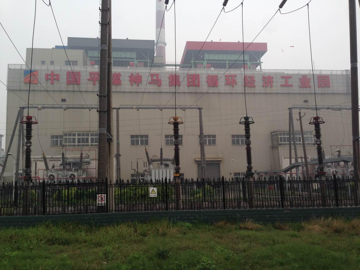
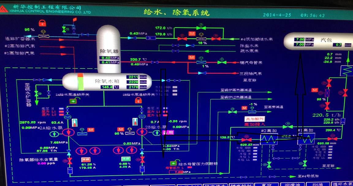
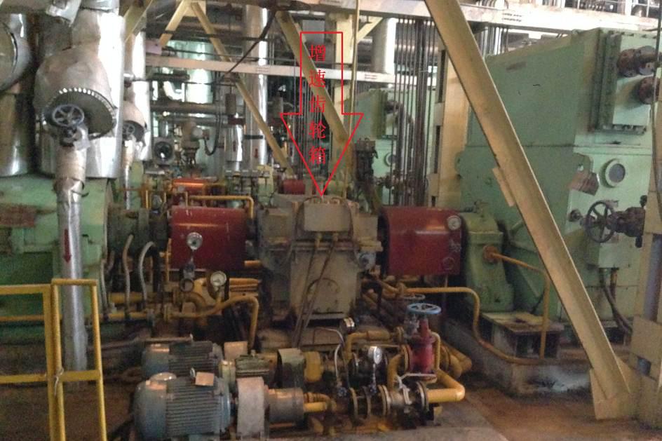
Second, the water pump system Each boiler feed water system supporting two 3800kW boiler feed pumps, a total of four units, a single feed pump flow 593m3 / h, head 1770m, with a use of a prepared operation program, a single feed pump that can meet The boiler runs at full capacity. The feed pump system consists of a motor, a fluid coupling, and a feed pump body (see Figure 2). The process flow is that after the deaerator's water is supercharged by the feed water pump, it is sent to the boiler drum through the high-pressure heater (in the direction of the black tip of Figure 3). The boiler turns the water into high-temperature and high-pressure steam by burning and heating, and promotes the steam turbine to do work. To achieve the balance between the steam of the boiler steam system and the water supply system. 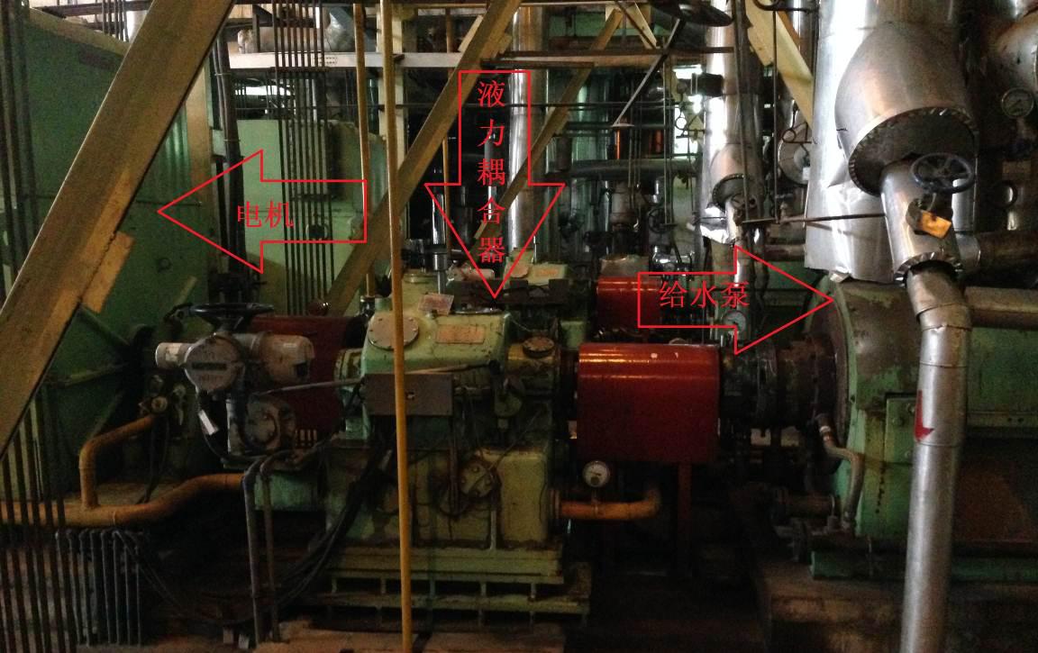
In order to ensure the stable operation of the entire boiler system, the unit changes the feedwater flow by adjusting the output speed of the feedwater pump's liquid couple before the rebuild to maintain the liquid level of the steam drum. Due to the higher speed of the feed pump, the fluid coupling mainly consists of two parts. One is the speed increasing gear. The role of this part is to increase the rated speed of the motor to the operating speed that meets the rated working condition of the feed pump. The second is the pump. The role of the wheel, turbine, scoop tube, and circulating oil system is to adjust the circulating oil through the scoop tube and change the oil filling amount in the coupling, thereby adjusting the turbine rotation speed and realizing the speed regulation of the output rotation speed. When the unit is in normal operation, a single feed pump is used to provide water supply and the other pump is in stand-by mode. Between the two feed pumps, the pumps need to be periodically pumped according to the regulations.
III. Feasibility Analysis 3.1 Existing Problems When using a hydrodynamic coupling to regulate speed, Ruiping Power Plant can meet the boiler water supply regulation function, but it has found the following problems:
(1) The use of a liquid-coupled transmission to regulate the speed of the feed pump has resulted in large transmission losses and low system efficiency, resulting in a large amount of energy waste.
(2) The range of speed regulation is limited to 50 to 95%. The speed is unstable. The high speed section reduces the output capacity of the equipment, and the low speed section affects the play of the energy saving benefit.
(3) low speed accuracy, poor linearity, slow response, not suitable for automatic control requirements;
(4) Liquid coupler governors work with high-pressure transmission oil and generate a large amount of heat loss during mechanical energy transfer.
(5) Although the motor can start without load, it still has about 5 times the impact current, affecting the stability of the power grid;
(6) Due to the existence of a relatively complicated oil system, the maintenance volume of the liquid couple is large, and the average maintenance cost of a single 4000 kW fluid coupling is approximately 20 W per year, resulting in serious waste of manpower and impact on production. At the same time, due to the large inrush current still present at the start of the hydrodynamic coupling, the system stability of the power plant will be affected. The technicians of Ruiping Power Plant are looking for a suitable alternative solution. After comparison and comparison, it is found that the current feed pump liquid is replaced by a high-voltage frequency converter. Even speed control, with a perfect solution. Compared with the liquid-coupling speed control scheme, the high-voltage inverter speed control system has the following advantages:
(7) Wide speed range 0-140%, high speed accuracy, fast response (8) high efficiency (greater than 96%), and stable at 96% above 20% load
(9) Real soft start can be realized without impact on the motor and power grid, and the failure rate of the feed water pump and motor can be reduced, and the maintenance cost can be reduced (10) The input power factor can be as high as 0.95 or more, and only a few reactive powers are absorbed ( 11) It is easy to maintain; the cycle of modification and debugging is short; when the fault occurs, the power frequency operation can be switched, which is applicable to the occasions where downtime is not allowed.
3.2 Advantages After determining the adoption of high-voltage frequency converters for transformation, Ruiping Power Plant began to inspect and screen major domestic manufacturers of high-voltage frequency converters. The high-voltage variable frequency speed control system of Leader Huafu Company has the following advantages over other products:
(1) Using a series-connected multilevel topology, the input and output harmonic content is small, the power factor is high, and the structure is reliable.
(2) Application of speed sensorless vector control technology, high control accuracy, fast response.
(3) Nearly 10,000 sets of product applications are the largest in the country, fully tested by the market, mature and reliable products, and low failure rate.
(4) The power plant has the most application performance, more than 3000 sets, familiar with the process conditions of the power plant, and has rich experience in the design of the implementation plan to ensure the reliability of the system. And there are successful experiences in the reform of the feed water pump. For example, the Datang Fuyang Power Plant with 300 MW units and Baotou Donghua Thermal Power users have come to investigate.
(5) 6kV/4000kW product rated current will reach more than 450A, will encounter a lot of design difficulties, and Leader Huafu company has rich experience in the design of high-power inverter, the equipment has been put into operation up to 18000KW, 5000KW power above There are more than 100 sets of commissioning equipment.
(6) Relying on the advanced management concept and quality control system of the world's top 500 companies and electric giant Schneider, the quality and reliability of the products have been greatly improved. With the advantages of the Group, the main low-voltage components in the cabinet are all Schneider products.
The feed pump is the most critical load of the boiler, and its reliable operation is certainly the first one, so the reliability of the product is also the primary consideration in the transformation. After a number of comparisons and comprehensive considerations, Ruiping Power Plant finally selected HARSVERT-VA06/490 products from Beijing Leader Huafu Electric Technology Co., Ltd. to transform four pumps.
IV. Implementation Plan The following two options are all feasible feedwater pump retrofit schemes:
Option one: The hydraulic coupling remains unchanged, the spoon opening to the maximum output, only carrying the transmission and speeding up. The inverter controls the motor speed through electrical characteristics to achieve the flow regulation of the feed pump. Since there is no dismantling of the fluid coupling, the maintenance of the fluid coupling also exists. At the same time, due to the efficiency of the fluid coupling itself, there is still a certain reduction in the energy saving rate.
Option 2: Remove the fluid coupling and replace it with a speed increasing gear box to achieve rigid transmission coupling; solve the problem of loss of efficiency in the mechanical torque transmission of the system. This method has a long period of construction in the early stage, and the investment will increase at the same time. However, the efficiency of the system will increase and the increased investment will soon be recovered.
Combining with the situation on the site, the preliminary design plan of our company is to disassemble the fluid coupling and increase the speed increasing gear box between the motor and the water pump. This can reduce the intermediate loss of the fluid coupling and make the pumping system the most efficient. However, due to the problems of the construction period and the gearbox manufacturer's delivery cycle, the end-user has retained three fluid couplings. When the inverter is controlled and operated, the coupling opening of the fluid coupling is 100%, according to on-site feedback. Under the same load, the current of the feed pump without dismantling the liquid couple is nearly 10A larger than that of the dismantling liquid couple. Therefore, Ruiping Power Plant still plans to remove the residual liquid couple during maintenance. 
On-site two unit 4 feed pumps, take the form of a use of a prepared, and all equipped with the inverter, when a feed pump fault, can immediately start the standby pump operation to supply water to the boiler, so the main circuit of the inverter adopts a Dragging a manual bypass solution is an economical and reliable primary loop solution. 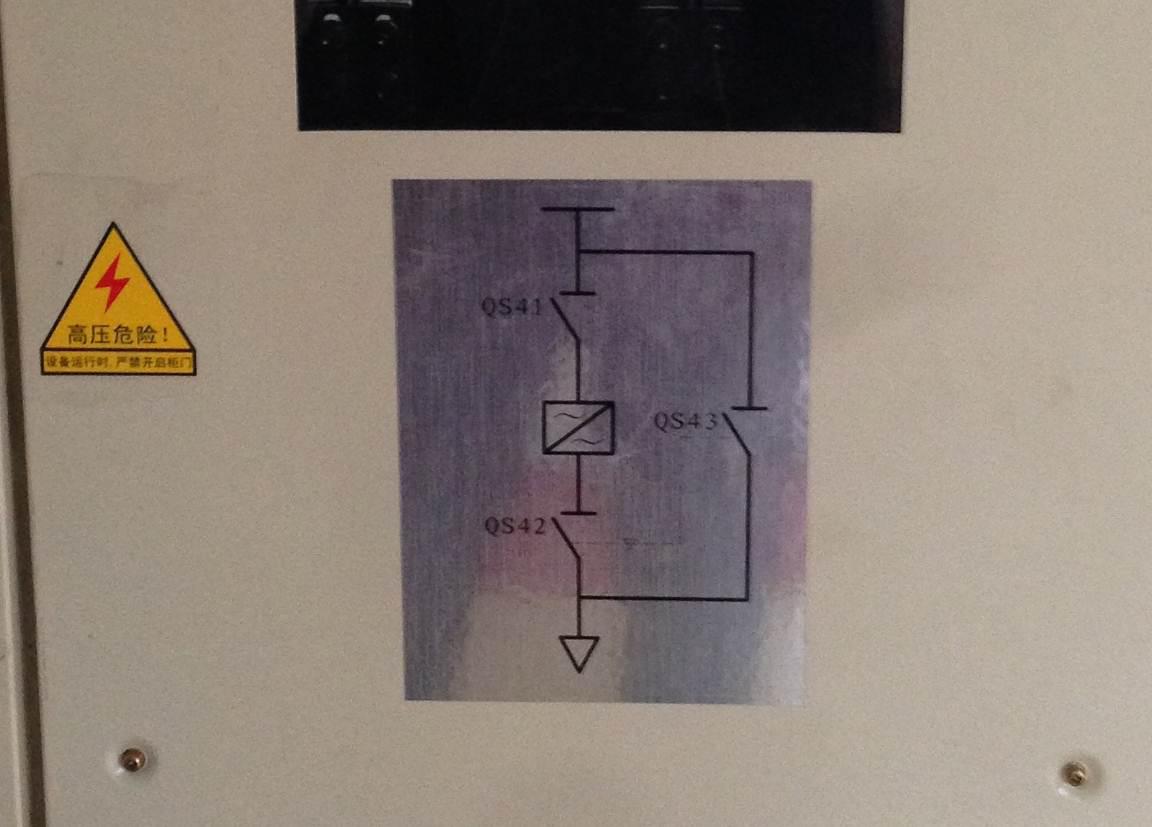
This scenario is a typical scenario for manual bypass. The principle is composed of three high-voltage isolation switches QS41, QS42 and QS43 (see the figure above). The mechanical interlock logic between QS42 and QS43 is required and cannot be closed at the same time. In frequency conversion operation, QS43 is disconnected and QS41 and QS42 are closed. When power frequency is running, QS41 and QS42 are disconnected and QS43 is closed. Function: When the inverter is checked and repaired, it has obvious power-off point and can guarantee personal safety. At the same time, it can also manually put the load into power-frequency grid operation.
V. Analysis of Energy-saving Benefits For the liquid-coupled speed-adjusting equipment before the frequency conversion of the system, the energy-saving calculation is as follows:
5.1 Calculation of power consumption at power frequency Pd: motor power; Cd: annual power consumption value; U: motor input voltage; I: motor input current; cosφ: power factor; T: annual operating time; δ: single load Percentage of running time Motor power consumption calculation formula: Pd=×U×I×cosφ...1
Cumulative annual power consumption formula: Cd=T×∑(Pd×δ)...2
According to the calculation formula 12, the power consumption of each load under the power frequency condition can be obtained through calculation, and the average power frequency operation power can be calculated by integrating the high-speed and low-speed operation time.
5.2 Calculation of annual power consumption in variable frequency state The required shaft power is the same regardless of the liquid coupling speed control or the frequency conversion speed control. The frequency conversion rear axle power formula can be derived: 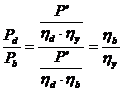 ...3
...3
Among them: power frequency power consumption for liquid coupling; power consumption for frequency conversion; power for load shaft; motor efficiency; liquid coupling efficiency; frequency converter efficiency.
It is known from the operating characteristics of the fluid coupling. ![]() ...4
...4
Among them: the actual speed, the rated speed of the motor.
Cumulative annual power consumption formula: Cb=T×∑(Pb×δ)...5
Where: Cb: annual power consumption value; power consumption for frequency conversion; T: annual operating time; δ: percentage of single-load operating time.
The efficiency curve of the frequency converter can be found from the figure below. 
According to the calculation formula 345, the power consumption of each load under variable frequency conditions can be obtained through calculation, and the average power of the device running under variable frequency speed regulation can be obtained according to the weighted time.
5.3 Energy Saving Calculation Annual Electricity Consumption: ΔC=Cd-Cb...6
Energy Saving Rate = (ΔC/Cd) × 100%...7
After frequency conversion reformation, according to formula 67, the annual power saving of each load after up-conversion can be calculated. 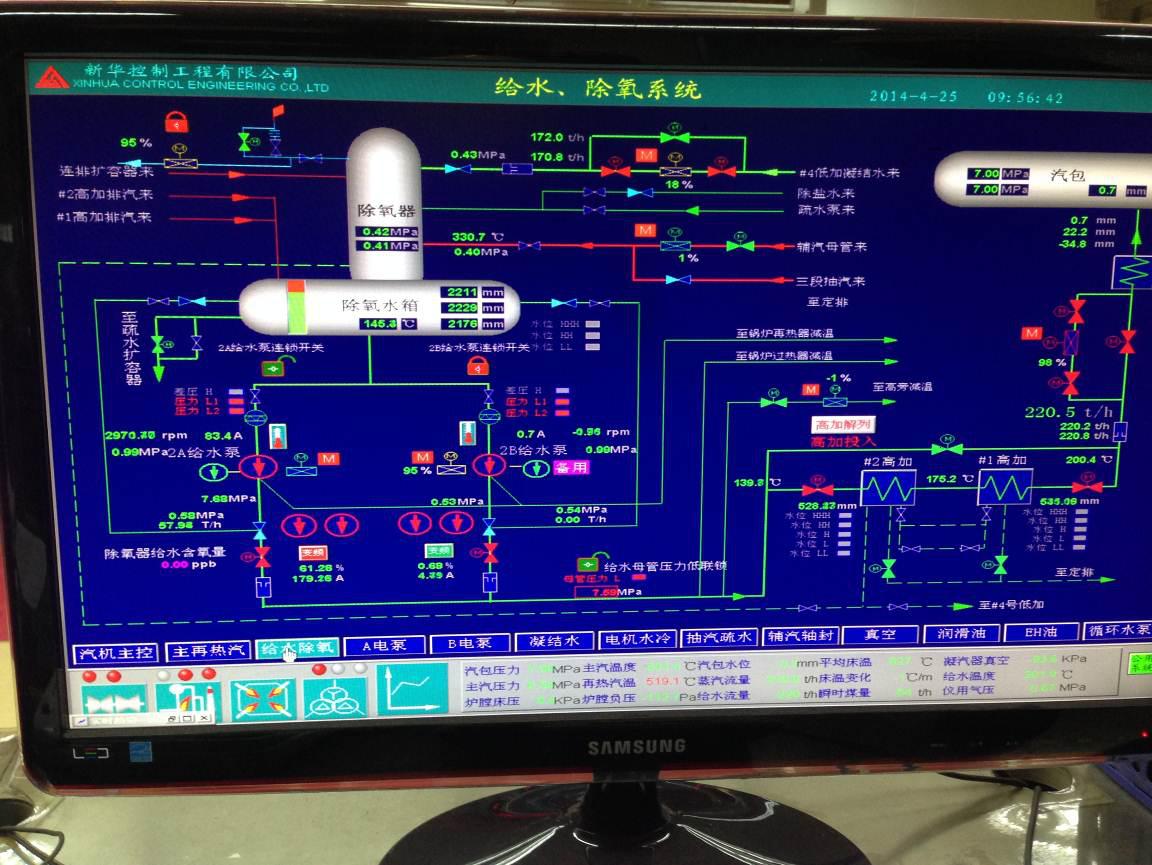
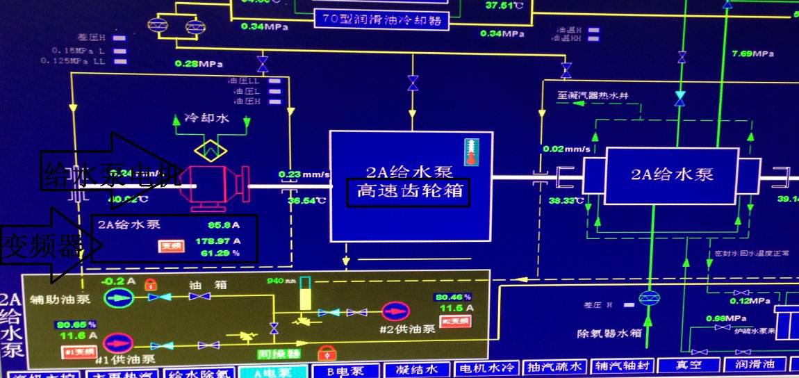
The image of the DCS collected by the site and feedback from the on-site operators showed that the unit operating load was 73 MW and the feed pump speed was 2974 r/min (rated speed 4725 r/min). If the original liquid couple was used, the speed was basically the same. According to the efficiency of the liquid couple, the energy saving rate at this speed can be calculated to be about 30%. The running conditions in autumn and spring are basically the same as those in the picture; the load in winter and summer will be slightly higher, reaching over 100MW, so the energy saving rate Will be reduced, about 15%.
VII. Summary With the deepening of energy-saving optimization of power plants, conventional air-supply fans, induced-draft fans, and condensate pumps have completed energy-saving retrofits, and power-plant reductions must find new breakthroughs. The feed pump as the largest power equipment of the boiler system is also the most important auxiliary equipment. Due to concerns about the reliability of the frequency converter in the past few years, basically no frequency conversion reform has been carried out, but with the development of the frequency converter in recent years, the technology gradually Mature and highly reliable, the various power plants began to intentionally attempt to transform the frequency converters of the feed pump. Through several examples of the transformation of the project, it was proved that the frequency conversion of the feed water pump was feasible, and the transformation program provided by our company was mature and reliable. The safe operation of the unit has no impact, and the economic benefits it brings are also considerable. The frequency conversion of the feed pump will become a hot spot in the energy conservation of the power plant in the near future.
The Application of Leader Huafu High-voltage Frequency Converter in Feedwater Pump of Ruiping 2×150MW Unit
I. Project Overview Henan Shengzhou Ruiping Coal & Electricity Co., Ltd. was established in June 2004 with a registered capital of RMB 1 billion. It is jointly invested by China Pingmei Shenma Group and Henan Tianrui Group in a ratio of 6:4. The joint venture company, the power plant is located in the Gannan Industrial Park on the south bank of Ganzhou City, was put into operation in 2007 and is a heat and power cogeneration unit approved by the National Development and Reform Commission. The business scope is power generation and heating, and the project construction scale is 300MW. The existing two are 150MW ultra-high pressure heating turbine generator set and two 480 tons per hour ultra-high pressure, reheat, circulating fluidized bed boilers, fixed assets of 1.2 billion yuan.
Figure 1: Overview of the factory area
Figure 2: Composition of feed pumps
Figure 3: On-site water supply system
Fig. 4: Retentive liquid image
Fig. 5: Remove the fluid couple and increase the gear box screen
Figure 6: Image of a gearbox on the site
Figure 6: Main circuit schematic
Figure 7 Efficiency curve of frequency converter
Figure 8 scene DCS screen shots