Tension Pulley,Belt Conveyor Take Up Pulley,Conveyor Belt Take Up Pulley,Cord Tension Pulley NINGBO TANSUO MACHINE MANUFACTURING CO., LTD. , https://www.tsjxidler.com
Gate Position Indication
In a hydroelectric power plant, the wicket gate on a Francis or Kaplan turbine plays a crucial role in managing water flow into the unit. By adjusting the position of the wicket gate, operators can control the speed of the turbine rotation and the amount of electricity generated. This image shows a series of generators housed within the Hoover Dam. Each generator is paired with a turbine beneath it, and water from Lake Mead is directed into these turbines to drive their respective generators.
The wicket gate consists of a set of adjustable guide vanes encircling the turbine, which direct the flow of water into the turbine's runner. The runner is connected to the generator shaft. These cross-sectional images illustrate the wicket gate (in yellow) at a minimal flow setting (left) and at full flow (right). The turbine runner is highlighted in red.

*Originally uploaded by Stahlkocher at de.Wikipedia.*
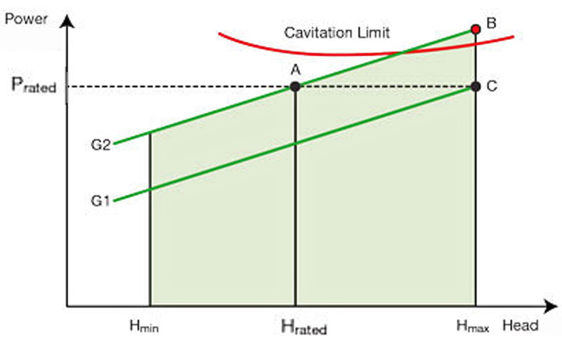
The output power of the generator depends on the head, or the height of water in the reservoir. On a graph showing power versus head, point A represents the rated electrical power output at the rated head, with the gate position set to G2. At this gate opening, a higher head results in increased power generation (point B), but there’s a risk of cavitation. To maintain optimal power output while ensuring safe operation (point C), the gate opening needs to be reduced to G1. Additionally, the gate position might be lowered further to generate less than the rated power during periods of low demand. Typically, the gate position is adjusted by a governor control, with the gate limit set by an operator.
A graphical representation of how gate position affects power output is illustrated below:
Early hydroelectric systems incorporated analog gate position indicators (GPIs). These devices utilized a precision potentiometer (or Helipot) attached to the wicket gate mechanism, producing a voltage output proportional to the gate’s position. This signal provided feedback to the governor control and was also displayed on an analog voltmeter. In some systems, the signal was routed through a current transducer to generate a milliamp signal for a remotely located 0-1, 0-20, or 4-20 mA GPI.
Basic gate position indicators only displayed the gate’s position, with the gate limit shown separately on a different dial or meter. This setup made it challenging for operators to gauge the gate position relative to the gate limit. However, systems like those developed by Woodward Governor employed dual-pointer meters to display both signals on a single dial. The black pointer indicates the actual gate position, while the red pointer shows the gate limit.
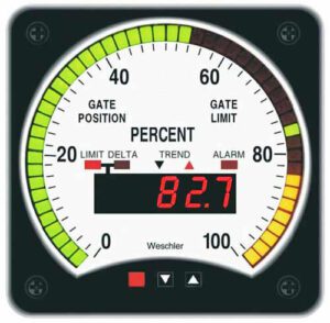
The modern digital equivalent of this meter is the Weschler Gate Position Indicator. It’s a specialized Tricolor BarGraph meter with two input channels, displaying both Gate Position and Gate Limit simultaneously in the LED bar. Operators can press the arrow button to view precise readings for position, limit, or the difference on the 4-digit display. Two relay outputs are available to trigger external alarms or execute control actions. The trend arrow shows the last direction of gate movement. Available in three case sizes—4½†switchboard, 8¾†switchboard, and 8†round—one key advantage of the bargraph display is its ability to clearly indicate if the gate position exceeds the gate limit. Here, the green gate position and yellow limit are shown, with any overlap highlighted in red.
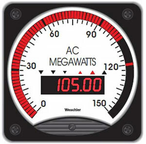
Modern hydro governors employ various methods for generator control to maximize performance under changing conditions. A separate digital gate position indicator, combined with a bargraph power meter, provides operators with a clear, intuitive status check of turbine operations.
If you need assistance with your hydroelectric systems or require any technical support, feel free to reach out to Weschler. They’re here to help!
---
Need Help?
Contact Weschler